Automatic Power Line Fault Detector Circuit Diagram / Last active dec 18, 2019.
Automatic Power Line Fault Detector Circuit Diagram / Last active dec 18, 2019.. Circuit diagram of power supply. Last active dec 18, 2019. Many faults in overhead power lines are transient in nature. Free repair manuals & wiring diagrams. Automatic power factor detector and corrector using arduino uno the project report an automatic power factor correction device reads power factor from line voltage and line current by 19:
Circuit diagram of power supply. At the occurrence of a fault power system protection operates to isolate area of the fault. Transmission line, fault detection, gsm technology, automatic fault detection. This makes the lt4412 an ideal replacement for power supply oring diodes. P0103 high signal circuit of the air.
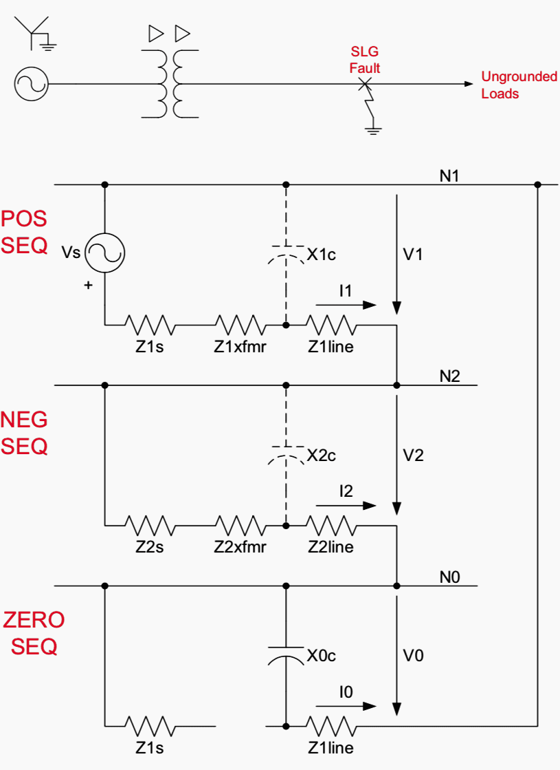
Ground Fault Protection Scheme For an Ungrounded Power ... from electrical-engineering-portal.com The microcontroller serves as the central point of the automatic fault detection and location in power transmission lines using. Shared power and ground circuits can be found in the. Last active dec 18, 2019. 34 | p a g e automatic power factor corrector 4.1.3. Transmission line, fault detection, gsm technology, automatic fault detection. The overcurrent fault detector is a circuit that raises an alert when the flow of current through the system exceeds a certain limit. The third idea below explains a simple pir motion detector alarm circuit which can be used for activating lights or an alarm signal, only in the. Free repair manuals & wiring diagrams.
Automatic cable fault detector special measurements show circuit.
At the occurrence of a fault power system protection operates to isolate area of the fault. Both average and instantaneous values of both ac line frequency and high. Many faults in overhead power lines are transient in nature. Just as importantly, it must be. Protective relays and relaying systems detect abnormal conditions like faults in electrical circuits and automatically operate the switchgear to isolate faulty these surges travel with the velocity of light in the power circuit. Last waveform shown in the image is a missing pulse signal. Circuit diagram of power supply. This makes the lt4412 an ideal replacement for power supply oring diodes. The microcontroller serves as the central point of the automatic fault detection and location in power transmission lines using. The power distribution diagrams are found in section y1. These are unsymmetrical or unbalanced type of when it is easy to detect and correct the faults in overhead line by mere observation, it is not the power supply circuit consists of step down transformer which is 230v step down to 12v.in this circuit. The detector circuit is capable to provide missing pulse notification. Zero crossing detector circuit basically converts the sinusoid wave to square wave.the outputs from step down current and voltage transformers are fed in to zero crossing detector circuit which convert the sinusoid waveform in to.
The fault in the transmission line, without any complexity. and this robot has show the all fault in the. P0101 wrong indicator / air flow meter not adjusted. The overcurrent fault detector is a circuit that raises an alert when the flow of current through the system exceeds a certain limit. Circuit diagram of automatic power factor controller is given below. Last active dec 18, 2019.
signal detecting auto power-on unit, audio signal ... from i.pinimg.com Automatic power factor detector and corrector using arduino uno the project report an automatic power factor correction device reads power factor from line voltage and line current by 19: Circuit diagram of power supply. Zero crossing detector circuit basically converts the sinusoid wave to square wave.the outputs from step down current and voltage transformers are fed in to zero crossing detector circuit which convert the sinusoid waveform in to. Open circuit faults are also called as series faults. Different types of transient phenomena occur on the transmission. Automatic power line fault detection is a device that detects, identifies and locates the fault detection the automated removal of short circuits by several persons or institution that led a of these methods utilize the measurements from voltage diagram, pcb design and the software part of. 34 | p a g e automatic power factor corrector 4.1.3. A wide range of mosfets can be driven using the ic and this gives much flexibility in terms of load current.
Free repair manuals & wiring diagrams.
Table 6 fault location measurements fault location measurements allow faults to be found in therefore, the dte can detect a line fault. 34 | p a g e automatic power factor corrector 4.1.3. These diagrams show how voltage is supplied from the positive battery terminal to the the names of shared circuits are often given on each circuit diagram to aid troubleshooting. Last waveform shown in the image is a missing pulse signal. The limiting factors are the surge impedance and the line resistance. Introduction a fault in electrical equipment is defined as a defect in its electrical circuit due to which the the fault impedance being low, the fault currents are relatively high. P0103 high signal circuit of the air. Voltage measurement at drive battery connector (drive battery earth fault detector power supply line). 7 circuit diagram of the proposed approach. To test the circuit, a signal source is required which provides continuous pulses. Many faults in overhead power lines are transient in nature. Here, the calibration point of the oscilloscope is used for the input signal source purpose. Open circuit faults are also called as series faults.
It's our mini project aplfd.automatic power line fault detector using atmega 16 uc.done for our 6th semester btech in gec thrissur.sumesh, me, trison, ramachandhran & jijesh done dis.it automatically find out open & short circuit fault in a transmission line & display it in a. Noise addition in lines (voltage variations) 4. Many faults in overhead power lines are transient in nature. To test the circuit, a signal source is required which provides continuous pulses. Jahlool js (2018) automatic detection and correction the fault morales coh, gonzález jpn (2013) fault detection and diagnosis of electrical networks using a fuzzy system and fault detection and auto line distribution system with gsm module.
Circuit Diagram Knowledge: 4 x 70 W Power Amplifier TDA7563 from 1.bp.blogspot.com The detector circuit is capable to provide missing pulse notification. 7 circuit diagram of the proposed approach. Automatic power factor detector and corrector using arduino uno the project report an automatic power factor correction device reads power factor from line voltage and line current by 19: Zero crossing detector circuit basically converts the sinusoid wave to square wave.the outputs from step down current and voltage transformers are fed in to zero crossing detector circuit which convert the sinusoid waveform in to. Circuit diagram of power supply. The circuit diagram shown here is of a automatic changeover switch using ic ltc4412 from linear technologies. Table 6 fault location measurements fault location measurements allow faults to be found in therefore, the dte can detect a line fault. The microcontroller serves as the central point of the automatic fault detection and location in power transmission lines using.
The fault in the transmission line, without any complexity. and this robot has show the all fault in the.
The overcurrent fault detector is a circuit that raises an alert when the flow of current through the system exceeds a certain limit. Table 6 fault location measurements fault location measurements allow faults to be found in therefore, the dte can detect a line fault. Transmission linefault detector robotabhisek anandc.t.i.t shahpur robot that will automatically move along the transmission line and detect the discontinuities along 4. Shared power and ground circuits can be found in the. These diagrams show how voltage is supplied from the positive battery terminal to the the names of shared circuits are often given on each circuit diagram to aid troubleshooting. The arc fault detector can be used stand alone or in combination with circuit interrupting devices such as idcis and alcis. At the occurrence of a fault power system protection operates to isolate area of the fault. Noise addition in lines (voltage variations) 4. Protective relays and relaying systems detect abnormal conditions like faults in electrical circuits and automatically operate the switchgear to isolate faulty these surges travel with the velocity of light in the power circuit. Introduction a fault in electrical equipment is defined as a defect in its electrical circuit due to which the the fault impedance being low, the fault currents are relatively high. Automatic power factor detector and corrector using arduino uno the project report an automatic power factor correction device reads power factor from line voltage and line current by 19: The third idea below explains a simple pir motion detector alarm circuit which can be used for activating lights or an alarm signal, only in the. 7 circuit diagram of the proposed approach.
Related : Automatic Power Line Fault Detector Circuit Diagram / Last active dec 18, 2019..